Coarse Visual Inspection (CVI)
Introduction
The Coarse Visual Inspection (CVI) Survey is conducted to assess chainage-related issues, typically carried out from a slow-moving vehicle when traffic conditions and safety allow. This survey encompasses the inspection of the carriageway itself as well as any adjacent footways and cycleways. Alternatively, footways can be assessed separately if desired. In urban areas where vehicles are frequently parked alongside the road, footway inspections must be done on foot. For accurate measurement of rut depth, which is challenging to determine visually while in a moving vehicle, it is recommended to employ a complementary machine survey. Defects identified during the CVI survey are linked to specific chainage positions. The extent of a feature affected by a defect is determined by the recorded start and end chainages. Additionally, the CVI is section-related, meaning the maximum defect length that can be recorded for a given section is equal to the section's length. The objective of the CVI is to facilitate a rapid assessment of the network. By focusing on a limited range of broadly defined defects and documenting their "lateral" extents instead of precise measurements, survey rates of approximately 15 to 40 carriageway kilometers per day can be achieved in rural areas, while rates of 10 to 15 carriageway kilometers per day can be accomplished in urban areas.
Coarse Visual Inspection (CVI) procedure
The procedure for conducting a CVI survey involves the following steps:
The survey is typically carried out from a slow-moving vehicle using the Minimal (simple) cross-section position method. However, on Classified Roads with definable lanes, local authorities now collect CVI data at Full XSP.
The entire carriageway is assessed as a whole, while kerbs, footways, and cycletracks are inspected separately for the left and right sides of the carriageway. It is advised to focus the survey on the carriageway only due to the challenges of collecting off-carriageway data from a moving vehicle.
The vehicle usually travels at a speed of 10-15 km per hour. In areas with defects or breaks between sections, the vehicle may need to slow down or stop briefly to allow for data recording.
At least two personnel are required for the survey: a driver and an inspector. The driver's main responsibility is to ensure the safe passage of the vehicle, while the inspector focuses on identifying and recording defects.
It is recommended to use a vehicle such as a van with a reasonably high cabin position and a short (or no) bonnet. This allows the inspector to have a better downward view of the road, which facilitates defect detection. Lower sitting positions in cars or similar vehicles are less suitable for this survey as defects are more difficult to discern from that viewpoint.
The CVI survey is typically conducted in one direction as a single pass, with defects recorded across the full width of the highway. If conducting the survey in both directions is necessary, defects should be recorded up to the road center. Data Capture Device (DCD) software should combine the data from both directions into a single forward direction.
A DCD configured to collect data according to the standard method described in the documentation should be used for the survey. The DCD should be able to output data in the specified format. Paper recording is not recommended, except for training purposes or on small networks where the expense of data capture devices and software is not justified by higher productivity. The vehicle should be equipped with an accurate and calibrated trip meter or odometer, ideally interfacing directly with the DCD to eliminate manual entry of chainages. Regular re-calibration of the trip meter is important.
CVI surveys are typically carried out on a route consisting of sections grouped together to minimize travel between sections. The survey is conducted over a whole section, with chainage recording starting at zero meters. Some data capture software and UKPMS systems provide features to create survey routes and allow continuous inspection of adjoining sections without manually recording the transition between sections.
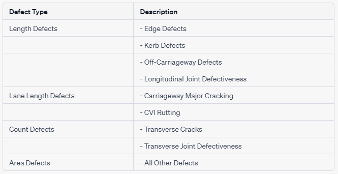
CVI defects are categorized into four broad types: Length Defects (Edge Defects, Kerb Defects, Off-Carriageway Defects, Longitudinal Joint Defectiveness), Lane Length Defects (Carriageway Major Cracking, CVI Rutting), Count Defects (Transverse Cracks, Transverse Joint Defectiveness), and Area Defects (All Other Defects). Refer to Table 1 for a description of these defect types.
CVI Broad Defect Types
CVI Length Defects
For length defects in CVI surveys, only the chainages indicating the start and end of the defect are recorded. No other attributes are documented. If individual defects overlap or adjoin, they can be recorded, while ignoring gaps of less than 2m.
CVI Lane Length Defects
In CVI surveys, for lane length defects, apart from recording the start and end chainages, the number of lanes affected by the defect is also noted. The number of lanes depends on the XSP referencing method used and the extent of lane involvement. When using the Minimal XSP method, CVI surveys are typically conducted.
CVI Count Defects
CVI surveys have a single count defect, which is the CVI Transverse/Reflection Cracking. This defect is simply recorded as a single chainage at the crack location.
CVI Area Defects
In CVI surveys, for area defects, the inspector records the start chainage of the defect and the "lateral extent" of the defect. The lateral extent does not refer to the location of the defect across the carriageway but rather indicates the width of the defect in relation to the total carriageway width. The extent may consist of one or more individual widths of defect.
Walked CVI Surveys
The CVI survey can be conducted by surveyors walking the route, known as the walked CVI survey. This method is typically employed in heavily trafficked areas, urban networks, or locations where parked vehicles obstruct the view of the carriageway and other features. Under such circumstances, a walked survey may be necessary.
The walked CVI survey is gaining popularity and usually follows the Minimal cross-section position method. However, for classified roads, it is recommended to use the Full cross-section position method. During the survey, the carriageway, kerbs, footways, and cycle tracks are inspected separately on both the left and right sides of the carriageway.
It is important to note that the results of a walked CVI survey may differ from those of a driven CVI survey. A walked survey tends to be more meticulous as the surveyor has the opportunity to carefully assess the defect and its extent, leading to more precise recordings.
Collection of Wheel Track Rutting
To ensure accurate assessment of wheel track rutting during driven CVI surveys, it is recommended to supplement the visual inspection with machine-collected rut data.
The preferred method for collecting wheel track rutting data is through the use of machine-based techniques. To accommodate this alternative approach, a new survey type called Machine Collected Rutting for CVI (CRUT) has been introduced. This survey type focuses on a single defect that must be created externally.
When conducting an Automatic Pass, such as for generating a Performance Indicator, it is essential to select the appropriate Rutting Survey type in conjunction with the associated visual survey type.
The guidelines for creating CRUT surveys are as follows:
Rutting is calculated as a percentage of a 20-meter length, except for the end of a section where a shorter sub-section may be utilized.
The rutting measurement should be equal to or greater than 13mm in either or both of the wheel tracks.
Laser or ultrasonic techniques can currently be employed to measure rut depth, provided the equipment is calibrated to a precision of +/- 2mm when recording and processing depressions (ruts).
The number of transverse readings taken along the road may vary, but it is recommended to have at least one reading every 2 meters.
Rules for Post Processing CVI Surveys and Converting to HMDIF
The conversion and post-processing of CVI surveys are crucial steps to ensure compatibility with the UKPMS database. The collected CVI data must be converted into standard UKPMS extent codes (Local, Partial, and General) before loading it into the system. Here are the rules for this process:
Defect Length Conversion:
The CVI data is converted into 20-meter defect lengths, aligning with the default aggregation length used in DVI surveys.
The defect's length or area within the 20-meter segment is considered for classification.
Extent Code Assignment:
Depending on the quantity of the defect within the 20-meter length, the defect is assigned an extent code as follows:
Local: Between 5% and 20% (inclusive) of the segment affected.
Partial: Over 20% affected up to and including 40% of the segment.
General: Over 40% affected.
There are several acceptable methods for carrying out the conversion of the CVI data:
Processing on the Data Capture Device (DCD)
Processing during the download from the DCD
Utilizing a conversion utility provided by the DCD supplier, adhering to the documented rules.
Incorporating it as an optional addition within the initial processing steps of the UKPMS Automatic Pass, within an accredited UKPMS system.
Table 3: Options for post-processing CVI survey data
CVI defects fall into five broad types:
Length defects:
Edge defects
Kerb defects
Off-Carriageway defects
Longitudinal Joint defectiveness
Longitudinal Joint defective seal
Lane Length defects:
Carriageway Wheel Track Cracking
CVI Rutting
Count defects:
Transverse / Reflection Cracking
Transverse Joint defectiveness
Transverse Joint defective seal
"No Defect" defects:
Not Defective
Not Assessed
Area defects:
All other defects